Custom Process Equipment & Skids
A process skid mounts vessels, pumps, valves, instruments and pipework on one steel frame, pre-piped and pre-wired and tested in the workshop, so it reaches site as a single unit that is set down and connected.
Product Categories
- Herbal, Botanical & Nutraceutical Extraction(9)
- Essential Oils, Spices & Oleoresins(6)
- Fruit & Vegetable Processing(8)
- Starch, Flour, Edible Oil & Food Processing(7)
- Drying & Dehydration Systems(5)
- Evaporation, Concentration & Solvent Recovery(4)
- Pharmaceutical & Industrial Process Equipment(4)
- Cocoa, Shea, Palm Oil & Oilseed Processing(6)
- Cereals, Tubers & Sugar Processing(6)
- Specialty African Botanical & Natural Ingredients(11)
- Specialty Food, Beverage & By-Product Processing(7)
Talk to Kadali Africa Ventures
Send your raw material, product and capacity for a technical proposal.
Contact Kadali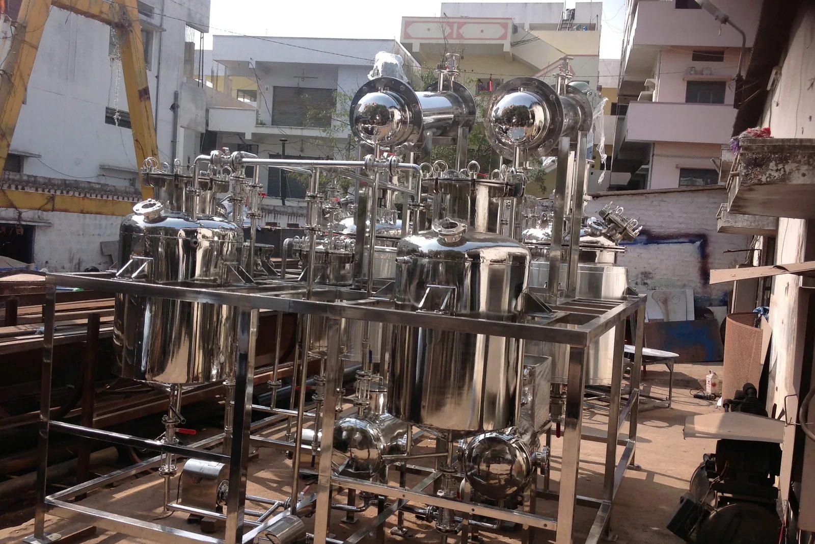
Custom Process Equipment & Skids
It suits repeatable, compact duties such as heating, dosing, filtration, cleaning, vacuum and transfer, and it does not suit tall columns, very large vessels or processes that rely on gravity flow between floors. Before a quotation, a buyer should settle the duty, the fluids and their hazards, the pressure and temperature, the material that touches the fluid, the transport route and any crane limit at site, and where the skid must tie into existing pipework, power and utilities. Those points set the frame size, the number of modules and the amount of work left on site. The price follows steel weight, the number of instruments and valves, and the engineering hours spent on drawings, far more than the capacity range shown elsewhere on this page.
The idea is to move assembly from the site to the workshop. A structural steel base carries the equipment in an arrangement that leaves room to reach every valve and instrument, with lifting lugs, a drip tray where fluids may spill and levelling feet or anchor plates for the floor. Pipework is welded or flanged and tested before dispatch, and instruments are wired back to a junction box or a local panel, so site work shrinks to a few process flanges, a utility connection and one cable entry. A skid is a good fit when the duty repeats, when site labour is scarce or the programme is tight, and when equipment can be run and tested on water before it ships. It is a poor fit for tall columns, large vessels that exceed the road or crane limit, and any process that needs gravity drainage. Large duties are split into modules that bolt together on site. Transport shapes the design more than most buyers expect: road width and height, port handling, crane reach and the centre of gravity of each lift are fixed at the drawing stage. The piping and instrument diagram should be agreed before fabrication starts, because a change after that point means cutting and re-testing finished work.
Indicative Capacity Range
- 0.5–20 m³ working volume
Key Specification Inputs
Design pressure, temperature, MOC, finish, applicable codes.
Technical Specifications
| Technology | Modular process package on a structural steel frame, with vessels, pumps, valves, pipework and instruments |
|---|---|
| Duty | Defined by the process: heating, dosing, filtration, cleaning, vacuum, transfer or blending |
| Frame | Fabricated steel base with lifting lugs, levelling feet or anchor plates, and a drip tray where fluids may spill |
| Wetted Material | Stainless steel, carbon steel, or lined or polymer parts, chosen for the fluid and the cleaning chemicals |
| Design Conditions | Pressure and temperature are inputs fixed before the piping diagram is frozen, not outcomes |
| Piping | Welded or flanged, tested before dispatch, with sizes and ratings listed on the tie-in schedule |
| Instruments and Controls | Pressure, temperature, flow and level devices mounted and wired to a local panel or a junction box for the plant system |
| Size Limits | Set by road width and height, port handling and crane reach; large duties are split into modules joined on site |
| Site Interface | Flanged process connections, utility points and a single cable entry, shown on a tie-in schedule |
| Workshop Testing | Water or air run with leak, loop and interlock checks against an acceptance list agreed beforehand |
| Utilities | Electric power, compressed air, steam, cooling water or nitrogen, as the duty requires |
Typical Process Route
Define the Duty and the Interfaces
Write down what the skid must do, the fluids, pressure and temperature, the available utilities and where it must connect. This sets the frame, the module count and the amount of site work.
Process Design and Piping Diagram
The piping and instrument diagram fixes every vessel, pump, valve and instrument. It is agreed and frozen before fabrication, because changes after that point reach the workshop as cutting and re-testing.
General Arrangement and Transport Check
The layout puts equipment on the frame with access to every valve, instrument and drain, then is checked against the road width, height and weight limits and the site crane.
Fabrication and Piping
The frame is welded, equipment is mounted and the pipework is welded or flanged, then pressure or leak tested. Gasket and seal positions are tied to the actual duty of each joint.
Wiring and Controls
Instruments and drives are wired back to a junction box or a local panel, labelled, and loop checked. Fewer field terminals mean fewer errors when the skid is connected on site.
Workshop Test Before Dispatch
The skid is run on water or air to find leaks, check pump rotation and prove interlock trips. A written acceptance list agreed beforehand keeps this test from turning into a debate.
Transport and Lifting
Loose items such as instruments are protected or packed separately, lifting lugs are checked for the load, and large skids travel in modules with their flange faces covered.
Site Setting and Tie-in
The skid is lifted onto a level foundation and anchored, then connected to process lines, power and utilities, flushed and commissioned with the plant.
Process & Equipment Modules
- Structural steel base frame with lifting lugs
- Drip tray or bunded base
- Process vessels and tanks
- Centrifugal or positive-displacement pumps
- Heat exchanger
- Valves, strainers and filters
- Pipework with flanged tie-in connections
- Pressure, temperature, flow and level instruments
- Junction box or local control panel
- Pressure relief devices
- Access platform and ladder for tall skids
Plant Output
Applications
- Steam, hot-water or thermal-oil heating skids for jacketed vessels
- Dosing and transfer skids for solvents, acids and additives
- Filtration skids on juice, oil and liquid-ingredient lines
- Clean-in-place skids for tanks and process lines
- Vacuum and condensing packages for evaporators and dryers
- Nitrogen blanketing and compressed-air packages
- Pilot-scale process skids used for trials before a full plant
- Process-water treatment and make-up skids
Key Features
Pre-Piped and Pre-Wired
Site work is limited to a few process flanges, utility connections and one cable entry, which suits sites with scarce skilled labour or a tight programme.
Frame, Drip Tray and Lifting Points
The base carries lifting lugs and a drip tray or bund, so the skid can be lifted by crane and still contain spills.
Transport Limits Built In
Road width, height, weight and crane reach are set at the drawing stage, and large duties are split into modules that join on site.
Maintenance Access on Every Side
Valves, instruments and drain points stay reachable, which avoids a tight, packed layout that is hard to service for years.
Tested Before Dispatch
Leaks, pump rotation and interlock trips are found in the workshop, where fixing them is quick and cheap.
One Tie-in Schedule
Flange sizes, utility points and cable entries are listed on a single sheet that site civil, piping and electrical teams all work from.
Related Products
Frequently Asked Questions
What information is needed to size Custom Process Equipment & Skids?
What capacity range does Custom Process Equipment & Skids cover?
What suits a skid, and what does not?
How large can a skid be before it must be split?
What tie-ins must the site prepare before the skid arrives?
Should the control panel be on the skid or in a separate room?
What can be tested in the workshop, and what cannot?
What happens if the design changes after the piping diagram is frozen?
How do I request a proposal for Custom Process Equipment & Skids?
Enquire about Custom Process Equipment & Skids
Send your raw material, target product and capacity to Kadali Africa Ventures for a technical proposal.