Solvent Distillation Systems
A solvent distillation system separates a mixed liquid feed into fractions by boiling point, using a still, a column with reflux, a condenser and receivers, so each fraction leaves at its own specification.
Product Categories
- Herbal, Botanical & Nutraceutical Extraction(9)
- Essential Oils, Spices & Oleoresins(6)
- Fruit & Vegetable Processing(8)
- Starch, Flour, Edible Oil & Food Processing(7)
- Drying & Dehydration Systems(5)
- Evaporation, Concentration & Solvent Recovery(4)
- Pharmaceutical & Industrial Process Equipment(4)
- Cocoa, Shea, Palm Oil & Oilseed Processing(6)
- Cereals, Tubers & Sugar Processing(6)
- Specialty African Botanical & Natural Ingredients(11)
- Specialty Food, Beverage & By-Product Processing(7)
Talk to Kadali Africa Ventures
Send your raw material, product and capacity for a technical proposal.
Contact Kadali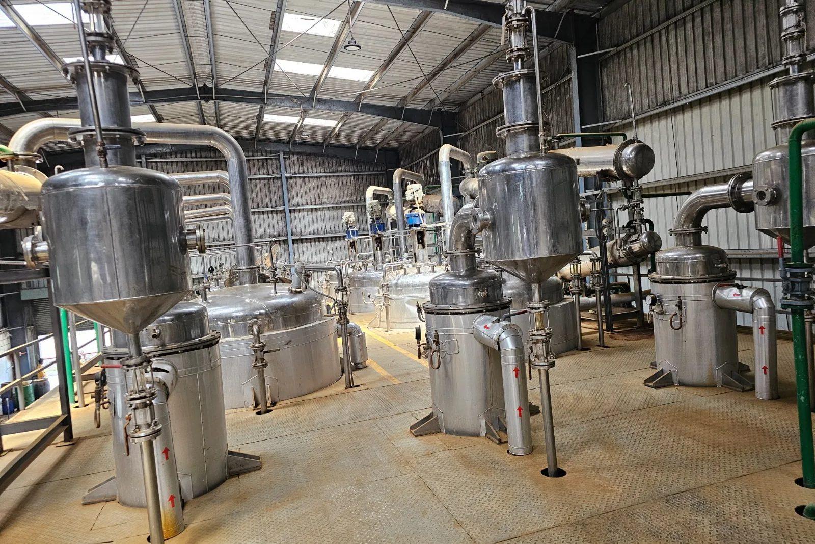
Solvent Distillation Systems
The feed may be ethanol and water from a botanical line, a drum of mixed solvents or a hexane stream carrying oil, and the plant either splits it into several products or polishes one solvent to a tighter purity. A buyer should settle the components and their boiling points, the vapour-liquid equilibrium data for the mixture, the purity wanted on each fraction, the feed rate per hour and whether the plant runs in batches or continuously. How hard the separation is sets the column height and the reflux, and the condenser and cooling supply, which carry most of the heat put in, set the main utility demand. Flammable solvents also make the classified-area layout a design input. Simple take-back of a spent solvent from an extraction line is the job of the solvent recovery distillation plant.
Feed is filtered or settled so that solids and colour do not foul the plant, then heated in a reboiler. Vapour rises through a column, where it meets liquid running down, and each contact moves the lighter component up and the heavier one down. Part of the condensed overhead returns as reflux and the rest is drawn off as product, so the reflux setting trades purity against energy and throughput. Components with close boiling points need more stages and more reflux, and some mixtures, such as ethanol and water, have an azeotrope that distillation alone cannot pass, which should be agreed with the process owner. Packing gives a low pressure drop and suits vacuum duty, while trays tolerate solids better. A batch column collects cuts in turn and suits varied campaigns and small volumes; a continuous column suits a steady feed with one separation. Reduced pressure lowers boiling temperatures for heat-sensitive or high-boiling feeds. Most of the heat put into the reboiler leaves at the condenser, so cooling water, air cooling or a chilled loop is a main utility, sized with the column. Where solvent and water separate into layers, a decanter splits them after condensing. Because the solvents are flammable, the area around vents, sample points and pump seals is classified, tank filling is made static-safe and vents discharge upward or clear of adjacent walls and eaves.
Indicative Capacity Range
- 50–3,000 litres feed/hour
Key Specification Inputs
VLE data, purity specification, reflux, pressure and condenser duty.
Technical Specifications
| Technology | Batch or continuous fractional distillation (rectification) of liquid solvent mixtures |
|---|---|
| Working Principle | Repeated vapour-liquid contact in a column with reflux, separating components by boiling point |
| Feed | Mixed or contaminated solvent streams, filtered or settled before the still |
| Column Internals | Structured or random packing, or trays, chosen by feed solids, pressure drop and the separation needed |
| Operating Pressure | Atmospheric or reduced, set by boiling points and the heat sensitivity of the feed |
| Reflux Control | Adjustable reflux ratio, set by the purity wanted on each fraction |
| Heat Source | Steam, thermal oil or electric heating, chosen by what the site has |
| Condenser and Cooling | Water-cooled, air-cooled or chilled, chosen by solvent volatility and local climate |
| Contact Material | Stainless steel, or another grade suited to the solvent mixture |
| Safety Design | Classified-area layout, earthing and bonding, static-safe tank filling, vents clear of walls |
| Automation | PLC control of temperatures, pressure, reflux and cut collection |
Typical Process Route
Feed segregation and analysis
Mixed solvents are collected by type and sampled for composition, water and dissolved solids. The analysis feeds the column design, since the boiling points of the solvent and its contaminants decide how hard the separation is.
Filtration
Solids and colour bodies are filtered out before the still, because deposits on heating surfaces and column packing cut performance and force shutdowns.
Staged evaporation
The feed is heated in the reboiler by steam, thermal oil or electricity, at atmospheric or reduced pressure. Heating is held steady, since surges carry liquid up the column.
Rectification in the column
Vapour and returning reflux liquid meet on packing or trays, which enriches the light fraction at the top. Reflux ratio, column pressure and temperatures are controlled to hold each cut at its specification.
Condensation
Overhead vapour is condensed in a water, air or chilled condenser, which takes most of the heat load. A cooling shortfall shows up as uncondensed solvent vapour at the vent.
Oil-water separation
Where the condensate separates into layers, a decanter splits solvent from water or oil before storage. Water that stays dissolved in the solvent is left for the column to handle.
Cut collection and storage
Fractions go to separate receivers by boiling range, and off-specification cuts are held for another pass. Storage tanks fill in a way that stops static charge building up, and their vents are placed to disperse vapour safely.
Residue handling
The heavy bottoms leave the still as a thick or pasty residue, so the discharge route and any need for vacuum are fixed in design. The residue is cooled before it is drained.
Process & Equipment Modules
- Feed tank with segregation by solvent type
- Filter or strainer
- Still with reboiler
- Column with packing or trays
- Reflux divider and reflux drum
- Overhead condenser
- Product cooler
- Oil-water separator
- Receivers for each fraction
- Vacuum system
- Recovered solvent storage with vent and static-safe fill
- Flame-proof electrics, instruments and PLC
Plant Output
Applications
- Separating ethanol from water in botanical extraction streams
- Splitting mixed solvent drums into separate usable solvents
- Polishing ethanol, acetone or hexane to a tighter purity before reuse
- Cutting a light head fraction and a heavy tail from solvent lots
- Splitting solvent and water layers in condensate from extract lines
- Pilot fractionation trials on a new solvent mixture
- Purifying solvent for nutraceutical and fine-chemical process lines
Key Features
Column Matched to the Separation
Column height, internals and reflux are fitted to how close the boiling points are, not taken from a stock size.
Controllable Reflux
An adjustable reflux divider lets operators trade purity against energy and throughput on a given feed.
Condenser Sized as a Main Utility
The condenser and cooling supply are sized with the column, since they remove most of the heat that goes in.
Static-Safe Storage
Receivers fill through a pipe arranged to limit static charge, with vents that discharge upward and clear of walls and eaves.
Flammable-Duty Layout
The still, vents, sample points and pump seals are placed and wired with the classified area in mind, and ignition sources are kept out.
Vacuum Option
Reduced pressure lowers boiling temperatures where the feed is heat-sensitive or the solvent boils high.
Country Pages for Solvent Distillation Systems
This product is listed on the pages of the countries below, each with its own enquiry route. Where Kadali has no office in a country, enquiries are handled from the Accra office.
Related Products
Frequently Asked Questions
What information is needed to size Solvent Distillation Systems?
What capacity range does Solvent Distillation Systems cover?
Should the plant run in batches or continuously?
What limits the purity of a fraction?
How much cooling does a distillation system need?
How is flammable solvent storage laid out safely?
What happens to the residue at the bottom of the still?
How does this differ from a solvent recovery plant?
How do I request a proposal for Solvent Distillation Systems?
Enquire about Solvent Distillation Systems
Send your raw material, target product and capacity to Kadali Africa Ventures for a technical proposal.